GENERAL DRILL & THREAD REFERENCE

TAPBASE

Find tap drill sizes for common SAE and metric threads. Use the quick lookup and browse the charts; printable shop references are coming soon.

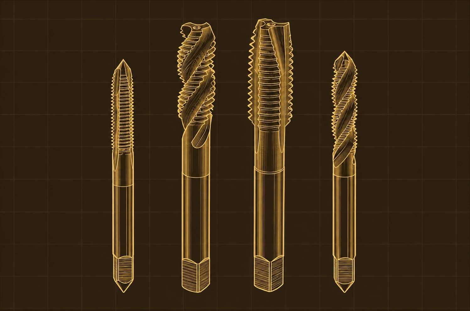
Brass blueprint illustration of four cutting taps
SELECT A TAPBASE SECTION
CHARTS & REFERENCES / INTERACTIVE TOOL

TAP & DRILL FINDER

SELECT YOUR THREAD

Common cutting-tap drill references only. Hole requirements can vary by thread class, material and tap manufacturer.
Not sure which thread or drill you have?

Start by checking the fastener diameter and thread pitch. Choose UNC, UNF, or the correct metric pitch, then verify the result against your tap and the material being threaded. Reverse Lookup is helpful when you already have a drill size.

RECOMMENDED TAP DRILL

For 1/4-20 UNC · Cutting tap
#7Drill size
0.2010″Decimal inches
5.105 mmMetric equivalent
20 TPI · Common shop reference. Verify application-specific requirements.
SHOP REFERENCE PRINTABLES

PRINTABLE DRILL & TAP CHARTS

PRINTABLE SHOP REFERENCES

Print-friendly shop charts are on the way.

We’re preparing downloadable SAE, metric, and drill-size reference sheets. The online charts and lookup tools are available now, free to use.

COMING SOONPrintable PDF collection
No downloads or purchases are available yet.
Below are early layout concepts for the printable charts. Final contents, print formats, and release timing haven't been announced.
PLANNED SET
04 / COMPLETE SET

Complete TapBase Shop Set

A planned collection bringing SAE and metric tap-drill references together with the drill-size index. The final contents and format are still being developed.

3 CORE SHEETSPRINT LAYOUT TBDDIGITAL FILES PLANNED
COMING SOON
SOCKETFINDERUSACHARTS & REFERENCES
SAE TAP DRILLS
UNC / UNF
THREADDRILLINCH
1/4–20#7.2010
5/16–18F.2570
3/8–165/16.3125
1/4–28#3.2130
SAMPLE PREVIEW · NOT FINAL PDF
MEASURE · MATCH · WORKTAPBASE
01 / SAE

SAE Drill & Tap Charts

A bench-friendly reference for common UNC and UNF thread sizes, recommended tap drills, and decimal-inch equivalents.

UNC + UNFCOMMON SHOP SIZESQUICK GLANCE FORMAT
COMING SOON
SOCKETFINDERUSACHARTS & REFERENCES
METRIC TAP DRILLS
COARSE / FINE
THREADDRILLINCH
M5 × 0.84.2.1654
M6 × 1.05.0.1969
M8 × 1.256.8.2677
M10 × 1.58.5.3346
SAMPLE PREVIEW · NOT FINAL PDF
MEASURE · MATCH · WORKTAPBASE
02 / METRIC

Metric Drill & Tap Charts

Covers common metric coarse and fine threads, with thread pitch, recommended tap drills, and decimal-inch equivalents.

COARSE + FINEPITCH INCLUDEDMM + INCH REFERENCE
COMING SOON
SOCKETFINDERUSACHARTS & REFERENCES
MASTER DRILL INDEX
FRACTIONAL • NUMBER • LETTER • METRIC
DRILLINCHMM
#7.20105.105
F.25706.528
5/16.31257.938
5.0 mm.19695.000
SAMPLE PREVIEW · NOT FINAL PDF
MEASURE · MATCH · WORKTAPBASE
03 / CONVERSIONS

Master Drill Size Index

A compact conversion sheet for number, letter, fractional, and metric drill sizes—useful alongside the tap-drill charts or anywhere drill designations need translating fast.

NUMBER + LETTERFRACTIONAL + METRICFAST CONVERSION REFERENCE
COMING SOON
Early previews only. The sample pages shown here are illustrations, not finished PDFs or downloadable products. There is no purchasing option or announced release date. The completed references will be listed here when ready.
CHARTS & REFERENCES / SHOP GUIDE

CUTTING TAPS VS. FORMING TAPS

Both tools produce internal threads, but use different processes. A cutting tap shears material away; a forming (roll) tap plastically displaces suitably ductile material. The tool, starting-hole diameter, lubrication and material requirements are different.

UNDERSTAND THE DIFFERENCE

HOW EACH TAP WORKS

ILLUSTRATIVE PROCESS DIAGRAMS
01 / CUTTING
REMOVES MATERIAL

A cutting tap uses cutting edges to shear metal into chips. Its flute and chamfer geometry help control chip flow as the thread is produced.

CHIPS
Produces chips; manage evacuation and chip direction
HOLE SIZE
Use the cutting-tap hole diameter specified for the job
BEST FOR
Many materials with the right tap geometry and cutting conditions
02 / FORMING
DISPLACES MATERIAL

A forming (roll) tap uses rounded lobes to displace ductile material into an internal thread profile without generating cutting chips.

CHIPS
No cutting chips generated during forming
HOLE SIZE
Generally larger than for cutting; tightly controlled
BEST FOR
Compatible ductile materials, with controlled lubrication

Conceptual cutaway diagrams only — not to scale, and not a depiction of specific tap tooth geometry or thread tolerances.

IMPORTANT / CUTTING AND FORMING HOLE SIZES ARE DIFFERENT

TapBase's general tap-drill charts contain common cutting-tap starting sizes. Do not use those diameters for a forming tap. Follow the specific tap manufacturer's hole-size range for the thread tolerance, material and target engagement; check the actual drilled hole, not only the drill label.

BEFORE YOU START

THREE SHOP CHECKS
  1. 01
    IDENTIFY THE THREAD

    Confirm thread diameter, pitch, standard and tolerance class; identify the exact cutting or forming tap.

  2. 02
    VERIFY THE HOLE

    Check the actual hole diameter, tolerance, depth and entry chamfer; allow clearance in blind holes.

  3. 03
    MATCH THE PROCESS

    Match tap geometry, alignment and lubricant to the material and hole type; plan chip evacuation for cutting taps.

FULL CUTTING VS. FORMING COMPARISONMaterials · Chips · Lubrication · Hole sizing
CONSIDERATIONCUTTING TAPFORMING TAP
How the thread is madeCutting edges shear workpiece material to create the internal thread profile.Forming lobes plastically displace compatible ductile material into the thread profile.
ChipsGenerates chips; correct flute geometry and chip direction matter, especially in blind holes.Does not generate cutting chips while forming the thread.
Starting holeUse the specified starting-hole diameter for the cutting tap, tolerance and application.Usually a larger starting hole than a cutting tap; tightly controlled to manufacturer data.
Material suitabilitySuitable for many material groups when geometry, coating and cutting conditions are appropriate.Requires compatible material ductility; brittle or unsuitable materials should not be form-tapped.
LubricationUse the specified cutting fluid or approved dry-tapping process; chip control remains important.High contact pressure makes the manufacturer-recommended lubricant especially important.
Through vs. blind holesSelect flute/chamfer geometry for hole type and intended chip direction; provide chip-clearance room in blind holes.Chipless forming can be useful for blind holes, but tap entry, depth and lubricant delivery still matter.
InspectionCheck the finished thread to its specified class using suitable thread gauges or the service procedure.Check the formed thread to its specified class; the final minor diameter changes as material flows.
Common problemsChip packing or incorrect flow, wrong hole size, misalignment and tool damage.Incorrect starting-hole diameter, incompatible material, high torque or inadequate lubrication.
COMMON SHOP QUESTIONSSix practical answers
Can I use a standard tap-drill chart with a forming tap?

No. A common cutting-tap chart is not a forming-tap drill chart. Use the forming-tool maker's hole-size range for the exact thread, material and required tolerance.

Can you form-tap aluminum?

Often, yes, in suitable ductile aluminum alloys. The alloy, temper, tool geometry, lubrication and application matter; verify the exact material against the tap maker's recommendations.

Does chipless tapping mean lubrication isn't required?

No. Chipless does not mean frictionless. Forming requires suitable lubrication or a specifically approved process to control friction, torque and tool life.

Can a forming tap clean existing threads?

No. A forming tap is designed to produce new threads in a prepared hole, not chase or clean existing threads. Use the Cleaning or Repair guide for an existing threaded hole.

Can I use the same tap for a blind hole and a through hole?

Sometimes, depending on tool design. Cutting taps have different flute and chamfer geometries that change chip direction and usable thread depth. A suitable forming tap may work in either hole type, but hole depth, tool design and lubricant delivery must still be checked.

How do I know the finished thread is correct?

Measure or gauge the finished thread against the required tolerance class and service specification. Smooth engagement by hand alone does not prove thread accuracy or strength.

TECHNICAL REFERENCES & SCOPETap-manufacturer guidance · What this page covers

This guide compares general cutting and forming methods; it is not a substitute for the exact tool maker's drilling, tapping and inspection data. Verify the workpiece alloy, tool specification, tolerance class, actual hole size and cutting or forming conditions for your application.

NEED A STANDARD CUTTING-TAP DRILL SIZE?

Tap-drill size does not determine tightening torque. For a separate general reference, see TorqueBase’s SAE and metric bolt torque charts. Use the joint’s specified tightening procedure when available.

TAP TECHNICAL ILLUSTRATION
Enlarged tap process illustration

Educational schematic · Not to scale · Consult tap-manufacturer tooling specifications for production work.